Factory Automation, Industry 4.0, and Switches: Part 2
By Mike Bolduc | June 26, 2017

In Part 1 of this blog, we reviewed sensors, or the “input” side of a factory automation system. In Part 2, we’ll discuss the actuators which carry out the work – and the control systems which make all the decisions.
Actuators
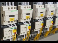
Once the sensors determine that everything is safely in the correct location, components are placed into fixtures and various operations – including cutting, stamping, riveting and welding – are performed. Actuators can be linear or rotary and be driven by electric motors or pneumatics. In order to function properly, these actuators use a number of devices for control and protection. With electric motors, overload relays and circuit breakers (or motor starters) are commonly used. These devices also typically require switches for setup and configuration. Tact and DIP switches (both standard and coded rotary) are commonly used to set output current levels and time delays and rotary switches are used to manually turn the device on or off. Miniature snap type switches are often used inside circuit breakers to determine trip conditions and send signals to a controller.
Relative to pneumatic actuators, valve terminals and valve controllers are used to power and control several actuators. These devices commonly use standard and rotary DIP switches for addressing and configuration. Similar to the switches used for factory automation sensors, these products need to be robust and be able to perform in harsh environments. Miniature footprints, sealing against corrosive fluids and low power consumption are also key requirements for the switches used on these devices.
Control Systems
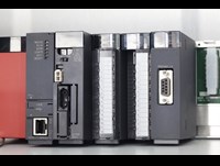
The control system takes input from various sensors and based on the control logic or program, sends signals to the actuators to carry out a variety of operations. Machine control can be carried out with a Programmable Logic Controller (PLC) or a Windows-based industrial computer. Additional components can include variable speed drives, servo-motor controllers, power supplies and communications devices such as Ethernet gateways.
Almost all control system components utilize some type of electromechanical switch for setup, addressing, or configuration.
PLCs for example, generally use either a slide or toggle switch to change from run to program mode at setup or when changes are made. General purpose variable speed drives often use standard and rotary DIP switches for configuration or to set network addresses. Embedded and industrial computers can use tact, pushbutton, or key switches for setup and operation. Finally, communication devices such as fieldbus modules and network gateways use a variety of standard and rotary coded DIP switches for configuration and addressing.
The various tact, DIP, slide, and toggle switches used on these control devices need to perform reliably for many years under harsh conditions. Attributes such as small form factors, resistance to corrosion and low power consumptions are critical for proper performance.
Once again, while these tiny configuration switches are only a smart part of the end device, they’re usually the part of the product the user interacts with the most – making them critical for communicating an image of overall product performance and quality to the end customer.
 |
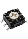 |
| Typical motor protection relay showing rotary switch | C&K RTE series rotary DIP |
 |
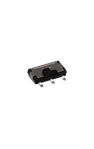 |
| Typical PLC showing slide switch | C&K AYZ series slide switch |

Mike Bolduc
Global Segment Manager
Industrial & Medical